Late in life, we tend to start "bucket lists". After reading about the sensational success of the F Class matches, my subconscious began to whisper "you can do that, you can do that". Along came an Eliseo stock in 308. Damage from a recent surgery blunder compromised my ability to withstand the recoil. The following year, my wife gave me a Winchester 52D for my birthday and I remembered shooting prone with the W52 many years ago quite successfully. So would not the W52 be good training for FClass? Access to a 130 yd range added justification, too close for FClass and precisely challenging for 22RF. Alex Sitman built me an excellent prone stock for the W52D. My Eliseo 308, chambered by by Pierce Engineering, defined the scope of work, an Eliseo-Winchester 52D stock. One for CF, one for RF training. Thus began a 3 year quest. And considerable naivete. One caveat, my profession is civil engineering and surveying. No one should assume that I have expertise as a machinist.
INTRODUCTION
My wife gave me a Winchester 52D for my birthday. Sanding, Sanding, sanding rub rub sand yielded an excellent looking stock. Then checker, checker and checker. The result was less than my expectations but more than my ability at the time.
 |
| Winchwester 52D after Stock and chamber "enhancements" |
Six months of shooting convinced me that the rifle looked good but would not shoot. Generally at 100 yds the groups would be 2" windage and 1" vertical on a good day that I did not make a mistake. Many times I could see the round going downrange rise 10" and spiral to the right into the target. Ammunition experimentation did not seem to offer an improvement and testing with harmonic tuners did not return repeatable reduction in group size. After much consternation, I decided to rebuild the W52. The barreled receiver was sent to Alex Sitman at MasterClass Stocks and after molding Alex returned the action. The action was then shipped to LA.
To the range with the 22RF: The rechambered barrel made a distinctive change in the group size...worse...now 7" at 100 yds. What a blunder and disappointment. The new chamber did not score the bullet nose. I knew the result before I fired it.
My instruction was to set the barrel back one thread and to rechamber with a Meyer reamer per Dave Kiff. One year later both the stock and barreled action were finally back in my hands. Several excursions with the Eliseo-Pierce 308 convinced me my 22RF effort was well worth it.
 |
| Figure -1- |
 |
| Figure -2- |
First, from my engineering experience, a numerical model of the receiver had to be constructed. The resulting computer model is shown as Figure -2-. The layout used to develop the "model" is shown as FIGURE -1-. Figure -1- was developed by wrapping the receiver with 0.003" bond paper gently tapping the surface with a wooden dowel. The second phase was cutting the indentations with an exacto knife and scanning the result at 1200 dpi. Thus the 2D "surface" represents the receiver 0.006" over diameter. From that point I wrote a computer program in Visual Basic 61 to convert the 2D representation into 3D coordinates and imported the resulting coordinates into Microstation2, a graphics production tool applicable to multiple disciplines, architecture, civil engineering, mechanical engineering and electrical engineering to name only a few. This created Figure -2-. Figure -1- was then scaled in the X direction proportional to the ratio of the (Stock OD)/(Recv OD). Once scaled the program resolved the detailed 2D dimensions into 3D. See Figure -4A-.
 |
| Cutting Loading Port |
Along with this the actual position of the cutting tool can be considered and careful consideration is required. As the tool penetrates the outer stock surface toward the receiver ports direct axial position cannot be assumed due to the diameter of the tool. Before recognizing this geometrical aspect my prior assumption caused removal of material not desired AND at least one prototype to the trash bin.
Before we get too far with the milling aspects of the project, all the lathe operations should have been very simple; however, my new Jet 13X40 GHL could not bore a hole concentric with an OD. Much of my complaints ignored.
SEE
http://www.jettools.com/us/manufacturing/en/product.html?node=4642&product=361822
The last set of definitions required the profile of the bolt lever and its intersection with the STOCK surface. Thus I started by measuring the profile of the bolt using the lathe digital readout and then translating those measurements related to the centerline of the receiver. See Figure 2. At this stage all the geometry has been identified for use in the 1) lathe or 2) on the mill. At least I thought.
RECEIVER-STOCK CONCEPT
 |
| Figure -4A- |
 |
| Cross Section at Rear Bolt |
 |
| REAR ACTION BOLT |
 |
| Figure -5- |
 |
| FIGURE -6- |
MACHINING OPERATIONS
The Lathe
 |
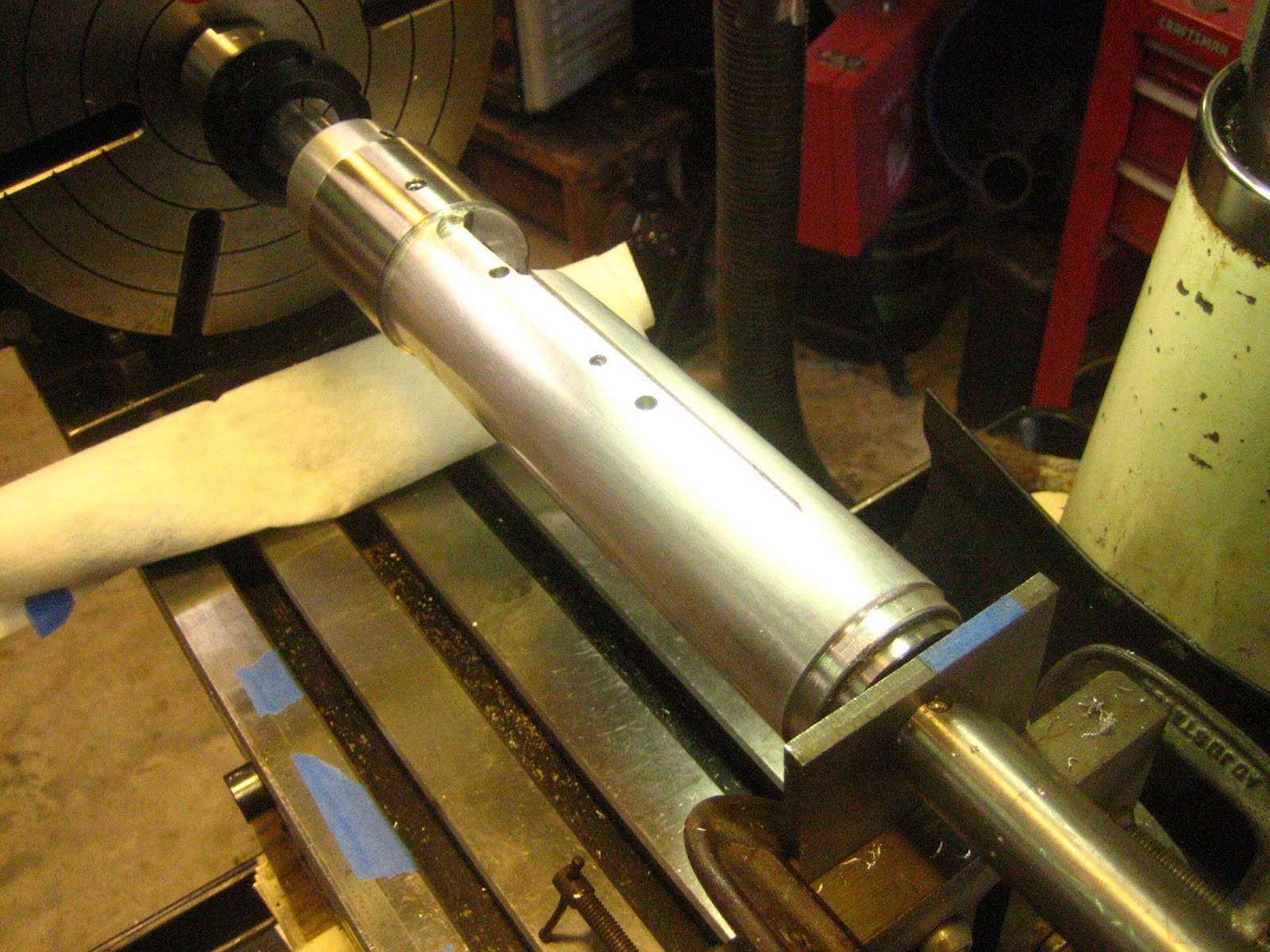
| Figure -7- |
The unfinished stock is shown in Figure -7- after final finishing to OD, both stock and the SS sleeve. Mandrels have been cut and finished for both the barrel end and the buttstock end. Buttstock is toward the reader.
The singlemost difficult aspect of the lathe operations involved boring a 1.230" hole into a 2" dia aluminum bar stock 10" long, uniformly. Jet Tools (3) can provide a medium priced lathe capable of precise work; however, for all you neophytes, be warned. The headstock vs. ways vs. tailstock will not be aligned. Furthermore they will not warrant the Q/C certification issued by the factory. The warranty period is 2 years. Realistically, this issue is beyond the scope of this discussion and regardless, from an involvement aspect, this issue created an unseemingly endless task of several hundred hours. Enough. More definitive descriptions will be later published.
 |
| Figure -7A- The End Bushings for the 1" dia shaft |
The Mill Operations
My mill is not really a mill, JET terms is a drill-mill. Drilling is easily performed. Milling is complicated by the motion (flexibility) of the stand. The motor torque at startup moves the quill location and vibration can damamge the work. The stand is inadequate. Plans are on hand to remedy this situation. Look at the mill-stock setup I devised, Figure 8. Let me explain. The rotary table on the left is 10" with a Shars ER-40 1" collet and MT3 chuck. On the right is an adjustable tailstock comprising a 1" thick angle bracket. Barely visible is a 1/4" plate,with 1.003" hole, clamped to the bracket. This jigging yields bi-directional location at the tailstock. The stock is now ready for all holes to be drilled (with some tapped). This phase of the build constituted many errors on my behalf. At this stage the system model has been defined as a 3D cartesian coordinate system (with Microstation). To make the rotary table most useful a 3D cylindrial system is advantageous so a cartesian to cylindrical system transformation was required.
 |
| Figure -8- Milling Jig |
Also, at this point I assumed all the holes and the slot for the sight ramp milled. I was incorrect which caused considerable trial and error cuts which, in retrospect, was wasted time and effort. I'll explain. My comfort with geometry was not followed through to the final step because I anticipated visualization of the final product. Well, this was not correct because I did not anticipate the proper position of the bolt lever arm slot.
 |
| FIGURE -9- |
The measurement of the bolt handle through cut was accomplished with the annular ring seen in Figure 4A. Also see Figure -7A-. The ID fits the receiver OD by +0.003". Orthogonal axes are scribed on the ring. Then the piece is placed on the receiver with bolt installed, the handle moved through the complete movement and the upper and lower limits marked on the ring.
 |
| Fig -11- Slot and holes |
The holes that Gary E used conflicted with positions of my action torque screws, and penetrated the bolt handle slot. The slot cut was too deep and a myriad of other complications.
 |
| The inside mandrel |
In order to facilitate all operations the inside mandrel must be smaller than the actual ID, 1.230 inches. The 1" round adds sufficient stiffness. At this point the coordinates must revert back to cylindrical coordinates that will be appropriate for the rotary table. One aspect at this stage: Once the part is removed from the fixture aligning vertical axis with the part is difficult. The horizontal axis was simple. Gary E told me the best is not to remove the part.

The final operation is cutting the grip.
See the whoops on the table! Not good.
1) Copyright Microsoft Corp., Microsoft Visual Basic 6.0, 1987
2) http://www.bentley.com/en-US/
3) http://www.jettools.com/us/manufacturing/en/about_us/contact_us.html