Monday, December 31, 2012

Continuation of the JET GHL 13X40

The below represents some of the final suggestions made to the writer concerning the misalignment of the headstock and the bed ways:

from Richard King to the author:

I am writing this so those who have the same issue down the line can check their machine if they do not have all the nice test bars.

When you mic the 2 collars and they are good and you can do the face test and it's good, your all set. But if they are off what is wrong? The bed has a twist or the head is out of alignment. If you have a precision level like a 199 Starrett that the bubble is .0005"/12 graduations. Or even a 99 with a .005" / 12". Set the level on top of the cross-slide or saddle so it is 90 deg to the bed ways, mark the place your sitting with a magic marker. If you can level the machine or slide a feeler gage under one end of the level so it reads level. Have the saddle cranked up next to the head-stock, (HS) remove the test bar we just cut, or if you didn't level / align the bed first, level it before you do the 2 collar test bar. Adjust the machine or level so the bubble rest on the center and on a line. If your using the .005" per foot get a magnifying glass and a super sharp pencil. Mark the level where the bubble rests.

Now crank the saddle back toward the tail-stock (TS) about an inch and then move it back to where it was sitting stop the cranking always moving the same direction. Re check the level. It might take a few tries. Then crank it down the bed as close to the end as you can, if you can slide off the tail-stock,. then crank it the direction you cranked it at the other end and let the bubble come to rest. Usually it takes 10 seconds. If it is off adjust the leveling feet. I read you said it is spot on with the leveling, but if it isn't level the bed or use a level to "align the bed" Leveling a machine on a Aircraft carrier is tough don't you think...so aligning the bed-way parallel to each other is the key. If your bolted to a bench you will have some issues with stability I bet, but do the best you can and shim between the bed and the bottom of the bed legs. If it sets on a cabinet, be sure to check all the bolts holding the cabinet to the bed are tight. I also like to see the bed sitting on leveling plates under the leveling bolts.
 I know you have these test bars and I looked for a dumbbell online and could not find anything online to even know what it looks like.


Now that you know the bed is straight / level / aligned...You take the test cuts on the OD of the Collar. What is you reading? If it's a under .002" (.001" per side from center axis line). I would twist bed out of alignment so the 2 collar test cut straight. If the collar is big on the right side or TS end the mount a dial indicator where your tool is on the center of bar, and put .010 pressure on the indictor, then tighten the front side TS end leveling screw so the indicator moves .002". I know what your thinking it would be 1/2 that, but it won't be. Take .002 and take another cut. It should be good or you can tweak it again.

When done tighten the lock nuts with 2 wrenches on the screws and take one more cut. If it is more then .002 then the head is probably out of alignment with the bed. I used to be a repair station for Jet years ago. For the most part the machines were not the best, but people got there monies worth. Usually someone can follow the directions when they buy a machine and all will be OK, but factories do screw up now and then too.

If you double checked to be sure the cabinet is tight to the bed and its leveling screws are snug. I see the on the Jet Web-Site the head cabinet has 4 leveling pads. On a small machine it's difficult to get them to twist the bed unless they are bolted to the floor. But if the machine was build correctly you only put an equal amount of weight on those 4 screws and leave them alone.
Now here is my effort and reponsee to Mr. King:


 Headstock measurement on right:


The tailstock side measurement is shown on the right. About 0.003" difference, which is what I have been telling JET for more than 2 years. The bar is a high carbon steel bar, very difficult to machine. It was not moved ffrom the headstock during the operations. I used an indexable carbide cutting tool. The space between the collars, specified by Mr. King, was reduced 0.050". A light cut (<0.001)was made on the HS collar using Warner Companies HS insert.  The cut on the right collar caused some chatter since it was (0.007 dia). I then made an additional 0.0005" cut on both collars w/o moving cross slide.


I suggest anyone interested see :

http://www.hobby-machinist.com/showthread.php/8924-Jet-13X40-Headstock-alignment-nightmare-with-Walter-Meier?p=87520#post87520

for further details.

Much has occurred since this post. The entire operation per the above procedure was completed and as inexperienced as I am, the final configuration took about 40 hours. This is posted on the Hobby-Machinist web site as shown above.
Two issues were found. At the suggestion of JET's tech, the 4 jaw chuck was replaced by a Rohm Industries independent 4 jaw chuck. This chuck was found to be seriously flawed after much consternation and time. Quite possibly the OEM chuck is probably adequate; however, the alignment process was completed with the Rohm chuck, so the entire process must be revisited. Rohm did, after much discussion, refund my investment, shipping but not the time. Subsequently, I purchased a top quality chuck (BISON) for the same amount. It has not bee installed and the bed realigned as of this date, April of 2013. Did JET fullfil their responsibility? No, in my opinion. Finally I just accepted the fact they were not. They did send reps to the site, but realignment remained incorrect. I do not think they knew how to complete the task. The bed was misaligned went it left the factory.

Saturday, December 1, 2012

Assembled Eliseo W52 & Search for Accuracy

I am 70 and so I reserve December for me and my bucket list; thus I am at my range (130 yds) and workshop close to Remlap, Alabama, my home. Each day I sit on the porch, drink my coffee and watch the Michigan imported deer wonder through and browse on the acorns from the 100 year old oaks. From this same chair I occassionally call coyotes, although rarely answered. I thank GOD each day he allows me this pleasure. This week is clear cool weather and the "system" is assembled. Some of the earlier posts expressed the opinion the assembled system would respond to the search for accuracy differently from the test frame designed and constructed earlier in the year. To recap, this frame was used to assist ammo selection so critical for a 22 RF. The final results analyzed using a computer program which analyzed scanned target(s) data to a high resolution and made statistical projections. Thw W52 seen in the photo has a standard OEM chamber, termed "the Winchester chamber".
    The Win 52 shown above is to be fitted with metallic sights in the final configeration, but for conventional testing a 10X scope has been fitted. This scope is about 25 yrs old and has turret knobs, expensive at the time and as I remember about $400. The rings are Burris and the ring base is custom made and not finished. Burris rings are the low profile; however, for this application medium are on order. The turner is my own design and the affect is not fully resolved. There will be a front sight "bloop" tube also to mount the front sight. Somehow it must be combined with the tuner (not yet designed). You can see the stuff that must be assembled (I need a UPS for the logistics) for shooting and is not lightly promulgated.

The Winchester 52 Tube Stock Presumption-Postulus
  Now a brief word on the tube configuration. Nothing is so strongly believed as that which is least understood. Now that was me. The entire premise for this project was that the tube configuration would modify the boundary conditions (add stiffness) to the wooden stock W52 assembly and result in enhanced accuracy. From my reading, the vibrations induced by the propellant occur during projectile travel and the harmonic vibrations occur afterwards, like a plicked guitar string. The guitar string is deformed and the released for its harmonics. Same with the 22 barrel. The initial forces are resisted by the innate strength of the system; whereas, the later motions ( think of living in LA) are aftershocks and depend upon mass and strength.

The trigger mechanism location severely complicates the fitment. Especially if the builder is limited in experience with the lathe and mill. Further, my failure to completely "model" the system cost many manhours due to unforseen conflicts. My final assessment is a U shaped configuration would reduce the effort considerably and yet allow my postulus that a "clamped" action would respond favorably. Prior posts show this section, Figure XX, http://winchester52.blogspot.com/2012/09/eliseo-winchester-52-testing.html . My assumption is based upon many years in private practice as an engineer-surveyor, whether the result is measureable is yet to be proven.


NOW THE TESTING FROM SANDBAGS

work-in-progress

Thursday, October 18, 2012

MY 13X40 Jet Lathe nightmare


OK here is the problem:

With a calibrated test bar, MT5 & plain end:

Position 1 at end of chucked bar:

You can see that the dial indcator is zeroed.


Now the cross slide has traversed 10" toward the headstock.
The allowable error is 0.0004" per 5".  So in this single obsevation ( out of 100s) it the result is nearly 10 times the allowble and 20 times that tested.


So now finally, look at this:
Added 12/24/2012:

Let me digress somewhat. This particular model in a pin headstock lathe, as shown above. Being a neophyte, I was somewhat unsure of the exact methodology to test for headstock alignment and being bullheaded, yes bullheaded, my thoughts were "I paid, they should provide the product". Well was I mistaken. From the above test report, presuming reports are real and not fabricated or pencil whipped,  this machine tests generally 1/2 of the allowable JET criterion.  From my limited experience, I deemed this excellent, so why was I so adamant?  The machine would not perform a simple 10 " headstock test and everything I did was wrong. Not 90%, but 100%.

My confidence in JET was negligible. Here is one example:

This is the furnished steady rest, supposedly scraped in.
It took a year to convince WM to replace the steady rest.

The first year of warranty I spent trying to get their attention and could not and finally, the retailer (dealer) was able to get a "tech" assigned, whereas Walter-Meier hired a subcontractor, Mastercraft Sharpening Setrvice, Laverne, TN. At this time, the warranty expired was 1 year of a two year term. Thus in the interim I proceeded to destroy my 3 jaw chuck and the 4 jaw chuck furnished with the lathe.

Here's what happened:

As I was trying to make some sense out of a complex situation:
  1. I would take a 1" bar and chuck up and face it with the 3 jaw chuck.
  2. then center drill it at the headstock, got to be right!
  3. Then extend the bar to the live center
  4. clamp into the 3 jaw chuck. 
  5. Machine the bar some distance and check diameter.

Presuming the headstock is aligned, everything should check end diameters, it didn't.

Look below at an exagerated scale. The green tailstock is in line with the check centerline. The 1" bar is flexible enough to bend when the jaws are tightened and the live center is locked. I kept doing this over and over, assuming they were correct, until I destroyed the 3 jaw chuck and it would not longer center. Then I switched to the 4 jaw chuck and it too was destroyed.  First of all WM is not responsible to ascertain if the customer is "qualified".  My background is engineering, 45 yrs, and I should have analyzed the situation correctly before now.  In all fairness, WM replaced the 3 jaw chuck and I purchased a quality 4 jaw chuck and would have destroyed it had I not realized something untoward was causing undue forces.  My $1500 4 jaw chuck would have gone by the wayside also. By the by, I went through 3 cheap live centers.
WM also had a dog in this fight. They should have reacted in a timely manner, aligned the headstock and replaced my 3 and 4 jaw chuck.  They took advantage of my situation by stalling as long as possible.

Now the whistle has not yet blown on WM and they have, tenatively, agreed to revisit the issue  since the lathe motor failed.  That is to be seen, since in doing so they will acknowledge culpability.

What am I going to do? Well, I am mildly physically impaired (much less than others), and the loooow down work is hard for me to perform. As recommended by others, my next goal to to begin the task.

Now, my suggestion is to be sure you have in writing any warranty issues with your retailer and their fiducial responsibility in warranty matters. In our state the vendor, not the manufacturer, bears the ultimate responsibility. Let the buyer beware of the irresponsibility I encountered with WM.

This is just getting started trying to find the error:


QED


Added 11-19-2012:

On 11-14-2012 WM sent a subcontractor to evaluate the headstock condition and to repair the motor capacitors.  They did so and addressed the headstock alignment issue. Here is their solution.

1) Use 4 jaw chuck
2) add aluminum shims (1/8") to jaw contact points on bar.
3) install 2 test guages after bar centered.
4) use chuck wrench extention to tighten the chuck jaws until alignmentt is acheived.
5) Me being a novice have never heard of this method.


 Let me know if anyone has used this procedure. I have serious doubts and my $1000 chuck will not be treated that way.

Saturday, September 29, 2012

Continued Testing

The above will be analyzed quantitatively at a later date. However, my concerns involving the harmonics of my test frame may be valid, but not significant. A full day of testing with other brands and the wolf was performed on Friday September 29, 2012. The receiver barrel combintion utilized prior was held constant. One change was made however; the headspace was reset. The headspace for the 4-W52 I own are all inconsistent and incorrect, including the one I had a 'smith in LA reset (The Sitman stock). The old theory "if you want somehing done right, do it yourself" predominates here. I am pleased.

This is just my opinion: The barrel-receiver is a commercial version and I dont think many were made. It is immaculate; unmodified it will not perform at 100 yds. My guess is that 60 years ago, the chamber, known as the W52 chamber, fit a specific ammunication manufacturer. I do not remember the ammo we were provided; thus none will perform today vs. Anchutz.  Furthermore, I suspect, the Rem 40x combo I have will also show the identical performance.

Ah Hah! Thus yesterday, my frame proved itself appropriate to ascertain the innate capability of the barrel-receiver combo.

Mike's W52 barrel tuner

Also note above: my crude  tuner shrunk the group vertically and maintained it windage. Hmmm. Should affect harmonics in both direction. Yesterday there wind conditions calm. 80^max, clear with startling azure blue sky.

So, now, back to my efforts to install the Shilen chrome moly barrel, i.e. thread and chamber as per Dave Kiff. I am going to turn the end to 0.745". Not on this combo, but on a CMP version with matching numbers.

later.

More Data Inches

      STDx   STDy   delX delY
RWS       0.4651 0.4416 1.5126 1.4548
RWS 30rds 0.400  0.510  1.532  1.791 9/29/12
Laupa X   0.4592 0.3998 1.5367 1.9374
ELEY TEAM 0.5524 0.3374 1.9518 1.0745

FED um22 0.4018 0.4083 1.4279 1.5819
FED UM22 0.346  0.352  1.455  1.351 9/28/12
FED 922A 0.4484 0.4559 1.7888 1.6606
FED 922A 0.527  0.383  2.024 1.559 9/29/12


Wolf EM   0.283  0.394  1.104  1.642  9/28/12
Wolf /T   0.400  0.468  1.402  1.545  9/28/12
Wolf EM   0.338  0.342  1.278  1.189  9/29/12
Wolf/T    0.458  0.381  1.686  1.598  9/29/12

Data Analysis

Al Harrels site, varmintal.com, has a wealth of information concerning 22 RF based upon 3D finite element vibration analysis.  These calculations are deterministic from mechanics of material theory.  Mr. Harrel calibrated the 6mm calculations with data provided by Esten to his analysis which enhances confidence in the results. These calculations give the reader a direction and the tendency of a specific change.

http://www.accurateshooter.com/guns-of-week/gunweek078/  This article essentially follows the directions given to me by Dave Kiff.  Dave recommended the Myers chamber;

and in addition I found Rifleman's Guide To Rimfire Ammunition,  Steven Boelter (2006). Steve fired over 30,000 22 RF and has some tests with the W52 chamber.

more to come


OK here is the prototype #1

Wednesday, September 26, 2012

Eliseo Winchester 52 Testing


GENERAL
After all this time the testing begins. Shown here is the prototype frame with the mount and the first, of three, W52 barrel-receivers to test. The frame has been revised three times since the one shown here; however, the concept remains identical. Really, this is the cullmination of three years of effort on my behalf and considerable engineering activities.  Initially, my efforts were with the Federal 711B, which the shooting community consensus seems to denigrate. This formed my baseline. Things must get better from this baseline. This investigation is NOT designed to test the ammunition but the barrel-receiver combo vs ammunition.

The absolute goal is to compete prone, while I still can; however, my intention is to be competitive and the Sitman stocked Win 52 is not even close, which involved more than a year to accomplish. First of all Alex Sitman is not known to be quick or punctual; however, the results are uncompromised and I possess a high respect for his work ethic and honesty. Essentially, I know I must rebarrel the Sitman W52; but I can just "drop in" a barrel action combo for my own practice and I'm running out of time. Later I will add a Shillen barrel. Bill Blankenship, 8 time US bulleye champion who I was fortunate to meet, once told me not to practice with unknown and questionable gear. So I had Jim Clark build me 3-1911's over a 5 year period, two of which I have sold. Getting back to the W52:

http://www.accurateshooter.com/guns-of-week/22lr-rimfire-ammo-comparison-test/

The results are fascinating to say the least. The tester observed: “I got some amazing groups, and some which are, frankly, are absurdly bad! This has re-enforced what I had experienced with 22 ammo in the past — that is being consistently inconsistent.”

The procedure utilized was based upon a thorough general testing of more than 100 types of 22LR in very "sanitized" conditions. See the Accurate Shooter link above.

CONDITIONS
Over a period of 2 weeks and three days of testing 1) concept evaulation 2) FED 711B testing and 3) selected available brands carried by Midway USA.  The distance is 100 yds. The weather was great: 60^ to 80^ with winds less than 8 mph at ground level.  September 15, 2012 and September 22-23, 2012.

20 shot groups were observed, although at times I miscounted and the count was 18 or 19. Standard deviation was computed for the group, center of mass and error from the mean. The position of each round was measure to within .003".  One brush through the bore every 20 rds. Yes, this is achievable and here is how.


Here is a Remington Target 1080 fps. I never did reproduce this after this group. The light line to the left of the scan is exactly 3.000" + or - 0.015". Very symmetrical.  The Rem round is very tight in the W52 chamber, any W52 chamber. It is dirty. I have fired several thousand, waste of money, and time, which I do not have.


The pixel size is 0.003".  The green dot is the center of the group. The dotted lines are one standard deviation.


Rem 09/15/12
                         del X delY
1 240741.034 239937.067 0.391 -0.988
2 240740.917 239936.776 0.508 -0.697
3 240740.749 239936.540 0.676 -0.461
4 240740.987 239936.279 0.438 -0.200
5 240741.143 239936.426 0.282 -0.347
6 240741.539 239936.754 -0.114 -0.675
7 240742.045 239936.577 -0.620 -0.499
8 240742.072 239936.342 -0.647 -0.264
9 240741.970 239936.233 -0.545 -0.155
10 240741.660 239936.108 -0.235 -.029
11 240741.360 239935.913 0.065 0.166
12 240741.556 239935.860 -0.131 0.219
13 240741.625 239935.829 -0.200 0.250
14 240742.299 239936.100 -0.874 -.021
15 240741.776 239935.634 -0.351 0.444
16 240741.553 239935.551 -0.128 0.527
17 240740.597 239935.615 0.828 0.464
18 240740.477 239935.919 0.948 0.160
19 240741.405 239934.950 0.020 1.129
20 240741.735 239935.104 -0.310 0.975
 4814828.4985 4798721.576
                           

                            Left   Dn
 240741.424 239936.0788   -0.8743 -0.9880
                           0.9475  1.1292
 0.4975 0.5345              Right  Up
           Extreme Spread  1.8218 2.1172 inches


From the above and based upon this group, 66 2/3 out of 100 of the shots should be 0.498" left or right and 0.534 inches up or down from the center of the group and extreme spread 1.82" and 2.12" respectively. This score is 199-4X if held perfectly. And the next 20 rds in that box, much less the next box, who knows?

How did I do this?
Each target was scanned at 300 dpi. The scanned document was loaded into Bentley's  Microstation V8 Series 1 (Autocad has the same capabilities). A program written in Microsoft Visual basic then interrogated the file and extracted the coordinates in inches and the Cg computed and the other characteristics developed.  Press the "Easy" button.m Well for one group.


 TEST FRAME

The test frame evolved for more than a year and I will discuss some of the assumptions devised during the use thereof. But first a limited portion:

711B 09/15/12 STDx   STDy  delX   delY
             0.6132 0.6731 2.1022 2.5787
             0.6170 0.5299 2.2099 2.0216
             0.5346 0.9687 1.9126 3.4397

Rem Target   0.4976 0.5345 1.8218 2.1172

RWS          0.4651 0.4416 1.5126 1.4548
WIN T22      0.4837 0.8626 2.0810 3.3120

Laupa CentX  0.4592 0.3998 1.5367 1.9374
ELEY TEAM    0.5524 0.3374 1.9518 1.0745

FED um22     0.4018 0.4083 1.4279 1.5819
FED 922A     0.4484 0.4559 1.7888 1.6606
922A w/bbl   0.6115 0.5230 2.2507 2.1063
tuner

From this stage VarmintAL pages gave me guidance with his deterministic evaluation of a 22LR with and w/o a tuner. Originally, my hope was I could "tune" one of the W52 action-barrel. He did not perform verification of his model as stated elsewhere; but, I am not a novice at finite element analysis, albeit from a structural design environment. Material mechanics is an entire different discipline. Whereas structural is based upon "satisfactory performance", engineering mechanics ascertains actual conditions. I bow to his expertise.

look at the final frame:

This picture is "busy"; this was the last day of testing. Beneath the shop rag is a 95 lb lead weight. I made another one, 53 lbs, for the front leg and then added the 2" structural angle as a diagonal brace. All these modifications intended to add stiffness to the frame. Without the barrelled action, the frame does not exhibit, after a good "whomp" any sustained vibrations, so it alone is independent. Add the barrelled action, give it a "whomp" and the vibrations dampen for 2 seconds.
Receiver-Frame Connection Figure-XX
All of this is dependent upon the bullet exit time. Look at the RWS above data, about 1200 fps. This was a minimal group, only 10 rds (all I had). 3 rds were fliers, but look at the other hits. So maybe the time of flight has improved based upon the naked barrel harmonics. This round deserves more investigation.
To the right is a photo of the action connection to the frame. As discussed elsewhere, the rear of the W52 action has minimal stiffness. The open frame cannot reduce this deficiency; whereas the Eliseo stocked W52 will engage the cylinder. Qualitatively, the barrel harmonics will be subsequently reduced. Maybe AL can tell me how much. This avenue is not complete and I will add more info.
Futhermore, the open frame may have exerbated the rear bolt weakness. See Fig XX.


 The above will be my final condition and the rear screw affect will be minimal; thus the conditions tested herein are the before condition.

Also, from the above data, the receiver-barrel tested will not get me into the top 5. Most likely I will have to rebarrel.

First I am going to test one more action.

Then try to compensate the barrel harmonics with a tuner using the high velocity and low velocity methodology discussed on Accurate Shooter forum.

These items to come in a subsequent post.

ABSOLUTE FIXITY IN A TEST FRAME
Lastly. 
Consider the absolutely rigid mount (as I have devised here) for a moment vs. the bench rest shooting community. Once again, fixity (if possible) would resemble the testing performed in England by a 22 ammo manufacturer. Their testing clamped a barrel in a solid steel frame attached to concrete. The action was aft of the clamp and only 18" of the barrel protruded. The postulation was measurement of the barrel end frequency with light. Now, this would be very rigid boundary conditions. Even the barrel was shortened and thus subject to high frequencies.

Did I do this very same thing, albeit a flexible barrel? I dont know.

Bench rest shooters slide on rails, on special front rests, on special bags to specific density. Only the trigger finger and the shoulder touches the rig. They shoot groups the size of the 22 projectile under consideration herein.

In retrospect, let us consider the frame I have devised. But the connections are elastic. Between 2 plates of stainless steel, we bond an isolation rubber, i.e. laminated elastomeric bearing. The plywood shown in the photo is replaced by this bearing(s). The clamp would be justapositioned above the bearing. I think this is the way VarmintAl is modeling his boundary conditions. Well worth the modification. 

See: http://winchester52.blogspot.com/2012/09/continued-testing.html
It seems as though my overactive engineering mind overestimated the degree of fixity. The comments above are valid theoretically, the magnitude did not affect final result.

Added 10-05-2012 9:05 AM

The above concerns are not an 'overactive engineering mind' as discovered by others and hundreds of man-hrs have been devoted to analysis.

See: http://www.varmintal.com/  for thorough compendium on deterministic prediction of muzzle movement and orientation. This study helps us visualize the parameters involved and the relative affects.

For actual testing see:

    http://www.border-barrels.com/articles/rimfire_accuracy/tuning_a_barrel.htm

   http://www.border-barrels.com/articles/rimfire_accuracy/velocity_dispersion.htm

The latter is a long discourse concerning the vibrations of a "fixed" base such as I have constructed. My thoughts on the elastomeric connections was incorporated.

My goal is to find a combination of ammo-receiver-barrel that will amke me competitive. One thing I have learned: there may be a seperate setup for 50 yds.

to Quote:

The test rig had been built to be a rigid 'barrel vice', but it was plain that bottom plate flexed due to the recoil force. When looking through the scope (attached to the top of the barrel clamp) the picture would 'jump' noticeably when the rifle was fired. Free recoil test gun 
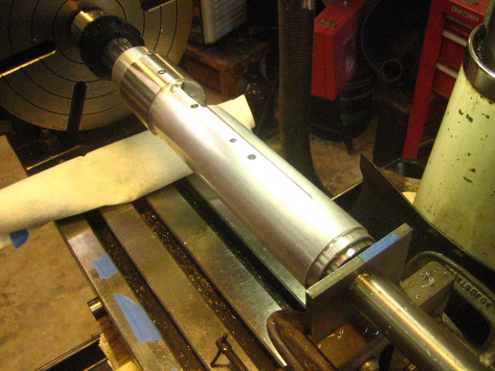
It was of concern that the recoil energy in the test rig was being dissipated in an unpredictable fashion into barrel vibrations that were affecting the group. In an effort to control the recoil energy in a predictable way, the Border Barrels Recoil Pressure Gun was adapted to make a free recoil test gun. With this gun, the recoil is constrained to be straight back, with the recoil energy being dissipated in friction by the linear slides on the rods and in the hydraulic damper seen at the back of the rig. The carriage is designed so that the centre of gravity of the recoiling mass is approximately on the bore line, so minimising any rotational moments when recoiling which might affect the launch angle of the bullet. Groups with this free recoil rig were initially disappointing as they formed vertical strings. The barrel and action were indexed 90 degrees to the left and to then to the right, but the groups produced were always strung vertically. Any systematic problem with the barrel and action was thus ruled out as the cause of the vertical stringing.

However, the barrel is vibrating before the bullet leaves the barrel. How we compensate is endless. This discussion used only two types of ammunition.  The 1/2" plate they used is flexible; my frame is flexible. However, I look at this in another manner. The frame(s) are very rigid; but the induced vibrations intiated by the burning gases transmits forces to the frames(s). Stocked and in the shooters hands, the results are more compliant. Consequently, we have only scratched the surface in 80 years for 22 RF.

End edit 10-05-2012.


A NOTE ABOUT W52 BOLT REMOVAL AND REPLACEMENT

 This topic is covered in many places; in no instance have I found an easy solution. One aspect is to understand the trigger. Look at this:
  • Everyone can remove the bolt, even in competition. So how do you get the blasted thing back in the receiver?  Push the easy button.
  • Look at the Photo to the right.
  • FIRST you must pull on the trigger to release the disconnector with right hand.
  • Second, hold the bolt in the right hand and aligned keeping finger on trigger.
  • Third, take the index finger of the left hand and with the nail down.
  • Fourth, Insert the finger into the receiver finger pointed to the rear.
  • Fifth, depress the top trigger lever with the thumb nail.
  • Sixth, with the right hand, while holding the trigger back, slide the bolt handle forward.  
This method was taught to me by the Army sargent supervising the UoA Cadet range. It takes practice. It works every time.

Mike
All rights reserved.


Friday, August 17, 2012

Alabama Deer Movements


THIS IS AN ARTICLE PUBLISHED IN A MAGAZINE IN 1982 AND I HAVE SAVED IT SINCE AS ONE OF THE BEST DESCRIPTIONS OF DEER MOVEMENTS. THE AUTHOR WAS DR. JIM BYFORD OF THE UNIVERSITY OF GEORGIA A WILDLIFE MANAGEMENT PROFESSOR. THIS DATA WAS EXTREMELY HELPFUL AND CERTAINLY STATE -OF-THE-ART. MAYBE SOMEONE ELSE CAN BE OF BENEFIT.

 
I've spent a good many years of my professional life trying to convince folks that deer don't leave their home range, and that their movements - like ours - aren't mystical. Deer movement patterns are keyed to fulfilling the animals' needs and to changing environmental conditions. But, you hear it every deer season, along about first frost, if you hang out where deer hunters gather. "I can't figure out where in tarnation deer go when the shoot in' starts. You see 'em all summer - and trails, too - you see trails wore clear down to bare rock! In summer, you can set your watch. They're down feedin' with Buck's cows at 8:15 every evening. But, I'm tellin' you, when fall gets here, most of 'em vanish, and the trails fill up with leaves. Must be the shoot in' that runs 'em out of the country. You know, it'd be nice if there was just some way to follow them deer around to see where they go .... "
Well, friend, there is a way - and it's called radio telemetry. I'll bet you've heard about it or seen it on TV. It involves putting a collar with a small radio transmitter on the deer's neck and - with the help of a directional antennae and a radio receiver - you can figure out in which direction the deer is located. By gel ting compass line directions for the deer's location from two points and plotting the two direction lines on a map, you know the deer is located where the lines cross. I, along with several other researchers, have studied deer movements this way. One of the researchers, Dr. Larry Marchinton at the University of Georgia, has been at it longer than any of us in the South. I've known Larry for several years and consider him a friend, as well as a very knowledgeable, in-depth researcher. Many of the facts in this article come from his findings.
Well, where do the deer go'? If you hunt in the South, the only place while-tailed deer go when the shooting starts , is "they go to hidin'," as one old-timer once told me. They don't leave their home range: they just change their movements patterns. In the southeastern U.S., the average white tailed deer spends its entire life on a little over 220 acres. In areas of very high deer populations, the ranges may be even smaller. The typical home range is only, about one mile long, and a little over one-half mile wide, and includes a variety of habitat types. For example, deer like crop fields, grass and clover strips, mature hardwoods for mast feeding, cutover woodland for green browse from root sprouts and shrubs, a water supply, etc. The more "mixed up" these habitat components are in an area, the more deer you're likely to find, because ranges of several deer will probably overlap.
It takes awhile for deer to find their way around when stocked into a completely new location. For a few weeks, I they'll wander around a piece of real estate, up to 10 times normal their home-range size, before finally settling down to a typical-sized range. Young deer learn their mother's range in just a few months. When the population gets dense, many of these young animals will wander until they find a new range in which to settle down - one without so much competition. This is called "dispersal," a phenomenon that has allowed reestablishment of white-tailed deer over much of North America.
Normally, when white-tailed deer are re-established, several deer are stocked in good habitat and the area is closed to deer hunting until the population builds. Hunting is begun on a limited basis (usually after about five years) while dispersal surrounding areas is taking place. As the population grows, both the season length and bag limit can become more liberal.
But, wait a minute! Don't get the wrong idea. Deer don't disperse because of hunting pressure - competition for food won't make them leave, either. In fact, they will often eat themselves right out of a food supply and starve to death before they will leave. Some studies have even found them to disperse from agricultural areas with abundant food to heavily wooded areas with less food. Hunting pressure isn't the whole story though. When they're hunted heavy, deer stick close to cover during hunting hours and do most of their moving in secrecy after dark. In areas where cover is scarce, they'll move more. within their range, due to hunting pressure. You may have seen deer under such conditions; if you have, you probably remember them as brown blurs.
So, if it's not food or hunting pressure, what makes deer leave? It has to do with that age-old, complicated, three-letter phenomenon - SEX. You have to understand that even though both does and bucks disperse, bucks do most of the leaving. Young does most often stay with their mothers; they have young, their young have young; etc. Eventually, they form a social group of two or three generations of does that pretty much travel together. But, up to 80 percent of the young bucks disperse from their mother's ranges the same year they are born - just prior to the rutting season. The few young does that do leave usually do so in the summer.
Why do most of the yearling bucks leave just prior to the rutting season? That's easy. They have just as much sex drive as the old boy with antlers growing out of his skull. They're not about to challenge him, though, so the yearling bucks go where sexual competition is not as great. Dispersal distances vary, but two to six miles is common. A great many yearling bucks are killed while wandering around a new range during dispersal. (Five out of six dispersing young bucks were killed in one study area.
A lot of hunters think that the Game and Fish folks allow too much buck-only hunting in old established deer herds, and that's why there aren't many bucks. This is not always true. If you stop to think about it, the older a population gets and the denser it becomes, the more the sex ratio will favor does - with or without hunting. This is because most does stay put and most bucks disperse under these conditions.
But, let's get back to home range.
It's common sense to recognize that deer are not using all their range equally all the time. When living conditions are better in one small part of the range, the deer spend most of their time right there, bedding, eating, watering, and all those other things deer do. These small areas are called "core areas" or "centers of activity." A deer's core area will change, from time to time, as habitat conditions change. One deer I followed around for three months changed core areas three times, and all the changes were food related. I first caught her in a grass clover strip where she spent most of her time. When corn became available, she moved her core area to the corn, spending all her time for several days in an area no larger than 10 to 15 acres. The corn played out about the same time that spring hardwood leaves began popping and she moved to a larger core area where hardwoods were more abundant than pines.
You've probably noticed, as I have, that hardwood ridges, littered with acorns, are covered with deer sign in the early bow season. But, come gun season, the fresh sign is down on the lower slopes. The ridge acorns have played out by then. find the lower slope oaks are just coming in. And, what about the heavy concentration of deer sign in a small spot'? Well, such a "hot spot" is where the core areas of several deer overlap. Be careful not to confuse core area actively with dispersal. Deer will shift core areas within their home range to gel to better food conditions, but they won't leave their home range for food.
Even though food is the drawing card that most often determines where core areas are located, other things do come into play. For example. does will set up core areas around their young fawns. One doe I followed had two core areas at the same time. One was centered around a spot where loggers were clearing timber; the leaves from felled treetops were the best source of food around the heavily browsed area. The other core area centered around a small stream where she would leave her very young fawn. returning several times each day to allow it to nurse. Evidently, she felt that the fawn was safer away from the loggers.
Another key factor for core area establishment is (here's that word again) sex. Dominant bucks - the ones that end up being the daddies of the fawn crop - establish small core areas of intense rubbing and scraping. At anyone time, one buck
Continued on page 50 September. 1982

• .. BUCK'S DOMAIN
Continued from page 40
may have several of these small areas within his home range; these are "dominance areas." Rubbing begins about one month before the rutting season actually starts, and these rubs serve to establish or delineate the dominance areas. Rubbing tapers off about the same time breeding starts. Scraping takes over to serve as communication between the dominant buck and does found in the area. The buck leaves his scent in and around the scrape, communicating, "sweetheart, if you're interested, stick around and I'll be back." Does in heat leave their scent in and around the scrape and "stick around." They hang around the scrape until the buck returns and then mating takes place. Sometimes, the old gal is coy and the buck has to follow her out of his dominance area, sometimes even out of his home range. When this happens, he of then invades the dominance area of another buck - that's when the fireworks begin. The area around the doe in heat is called the "intolerance zone." It moves with the doe. Dr. Marchinton tells of one buck that followed a doe in heat for three days and ended up about one mile from the scrape where the courtship started. When he returned to his own dominance area, he was cut, gouged, and bleeding, but as Larry put it, "He had a satisfied look on his face."
A dominant buck may move from one dominance area to another fairly regularly, until he finds a willing doe. On the other hand, he may spend several days in one dominance area, if several does in heat are hanging around. Sometimes, dominance areas of two or more bucks can be found close together. When this happens, the scraping and rubbing becomes more intense. A dominant buck will allow subordinate bucks to pass through his dominance area, as long as they stay in their place and maintain a subordinate posture.
Let's take a look at daily movements - all important from your point of view as a hunter. Deer researchers measure movements during 24-hour periods. These movements are called "diel movements". Diel movements of deer in the southeastern U.S. average about 1 1/2 to 2 miles total distance. This means that if you add up the total distance a deer travels from noon on one day until noon the next day, the typical deer travels 1 1/2 to 2 miles. Most of this distance is covered while meandering throughout the core area. On the average, the distance between the two extreme points during a diel period is about two-thirds mile. If food conditions are especially good in a small area, the diel movements will be much smaller.
Let's get one other thing out of the way: many folks think that deer always have feeding areas separate from bedding areas; this is true only in some cases. A good example where this would be true is where the best food supply - let's say a soybean field - is not located close to good bedding cover. In this case, deer would use the open field at night, and the bedding cover and feeding areas is a good way to ambush deer late in the afternoon or early in the morning. However, as the hunting season progresses, deer will move more and more under the cover of darkness.
In most cases, deer will bed in the vicinity of their food supply. Deer are primarily browsers. They feed for short periods, bed and ruminate (chew their cud) feed for a while, bed and ruminate, etc., throughout the diel period. At night, in the cover of darkness, I have often seen feeding deer just suddenly flop down in the open with no cover in sight. It is true, though, that deer sometimes have favorite bedding spots. If you find a buck in a spot more than once just prior to the season, this may be a good place to be at sunrise on opening day.
Some deer are moving at all hours during the day and night. When deer aren't disturbed often, much of their feeding in the summer occurs between 6 p.m. and 10 p.m. In the fall, undisturbed deer are most active at dawn, with movement continuing until noon. It may surprise most hunters to know that undisturbed deer move about twice as much during daylight as at night, throughout the year. But, as fall progresses, deer in agricultural areas move proportionately more at night. Why? Food is plentiful in the woods in the summer, so deer don't have to move far to feed, often bedding close to their food supply. In the fall, especially before acorn drop, less food is available in the woods, and more is found in open agricultural fields. Deer move out to these agricultural areas, but they have to wait for the cover of darkness. The ratio of night and day movement is about the same for does and bucks. Bucks tend to rub and scrape most in late afternoon, but buck movement between dominance areas is done rapidly, and primarily at night.
Now, when hunting season gets underway, the plot thickens. Man's activities, whether hunting, logging, or other cause deer to bed more during the times of human activity, and move more when the activity stops. One deer, which I followed around in an area being logged, usually bedded most of the day within about 200 yards of chainsaws whining, skidders spinning, and loggers yelling. At 4 p.m., when the loggers went home, this doe would begin moving going from one downed treetop to another, browsing on leaves. She would usually cover enough ground during the peace and quiet to make up for her inactivity during the daylight. Occasionally, she would be jumped from her daytime bed by workmen, but after running a short distance, she would bed down again. Other researchers have found that during heavy hunting pressure, deer in areas with plenty of cover will stick tight until the hunters leave, then move freely after dark. On the other hand, deer in areas where cover is scarce will dart from place to place during heavy hunting pressure - giving hunters a lot of practice at moving targets.
There's still a lot to be discovered about deer movements. But on the other hand, a lot has already been discovered. By putting some of this knowledge to work, getting to know your hunting place well. scouting just before the season opens, and using a little common sense - your chance of success will be far greater than that of the average hunter. Oh, one other thing - good luck:  September 1982

Thursday, August 9, 2012

Sparkplug Color


LEAN-Absence of color on plug with slight graying of porcelain. To correct, increase fuel jet sizes.
LEAN, HOT -No color and black spots, (oil) built up on porcelain. Cure: install a colder plug and richen fuellair mixture.
HOT -Absence of color on porcelain with dark shade on shell. Silvery-brown on ground strap indicates close mixture.
HOT, RICH-Black soot on shell and dark gray earth strap. Clean porcelain indicates too hot plug heat range. Colder plug and leaner fuellair mixture are required.
RICH-Good porcelain color with sooty-black shell. To correct, lean the fuel air mixture.
COLD, RICH-Porcelain and shell show heavy black deposits. Install warmer plug and lean fuellair mixture.
COLD-Black and sooty porcelain, shell shows normal dark color. Warmer heat range plug is required.
LEAN, COLD-Shell is clean to very slight coloring. Porcelain and ground strap are sooty-black. Correct with warmer plug and richer fuellair mixture.
HOW TO READ SPARKPLUGS

From Motorcyclist Magazine Dated sometime in the ‘70s
There's more witches brew and wives' tales associated with the art of reading sparking plugs than the number of tricks that can be found deep down in "The Magician's" famous black bag. On these pages we unravel all the mysteries, putting the spark plug in its proper place.
By Dave Ekins Photography/Pat Brallier
HOW many times have you had the spark plug out of your motorcycle? More times than you care to remember? Now, when you removed that plug was it simply to see if you were getting spark? Or maybe to determine if the motor was too wet to start? How about dry, no fuel at all? All this spark plug fiddling isn't necessary.
If you've got the correct spark plug you can leave it in there for a year and not even bother with it. If you're a racer then you're gonna pull the plug out every chance you get just to see if the engine's runnin' right, like all those other racers. It's all in knowing what's right. There are a few men who've made a profession out of reading spark plugs, but you can count 'em on the fingers of one hand. These guys are so scientific they can tell you if your points are dirty just by looking at a spark plug.
To begin with spark plugs come in heat ranges. There're also thread sizes, reach, and electrode style, but the part that concerns us is the number that refers to heat.
A B9E NGK for instance deciphers like this: B is for the 14mm thread, 9, the heat value and E is the 3/4" reach.
NGK's D8H for the Honda; 12mm thread D, 8 is the heat value, and H means a 1/2" reach.

The accompanying page gives us a picture of what a plug should look like when subjected to various conditions. It also tells us what these conditions are. Keeping it simple, the main reason one of us would want to make a spark plug reading would be to check for proper carburetor jetting, since we should be running the plug heat range recommended by the manufacturer.
If we've gone up in altitude the plug should give us a rich reading and we should change to a smaller main jet. (Changing needles, pilot jets, and slide cut-a-ways gets us into carburetor tun- ing and that's not our bag on this page.) Getting closer to sea level would require us to go in the other direction, richer, or a larger main jet.

We've also included a few pictures showing the wrong plugs in a given situation but this is just for a better understanding of what you might run into. It's all in the color and to make sure you've got the proper reading the engine must be run full throttle in the upper gears for a short time and then cut off cleanly, coasting to a stop. You should be looking at the plug with a 5x magnifying glass that lights up the subject; Champion among other people makes and sells 'em.
But before you load up that bike and take it out on your favorite deserted tuning road there're two things you had better look at first. Service the air filter, a dirty one won't do you a bit of good. Check the ignition timing, and while you're at it run an emery board or file across the points. You can get some horrendous spark plug readings when your ignition timing is way off and the air filter's acting like a choke .•
Spark plug in center is ideal condition. Porcelain can range from a light brown to dark chocolate, with the darker shade favoring 2-stroke-type engines.

Friday, March 23, 2012

BUILDING THE ELISEO-WINCHESTER STOCK


SUMMARY

Late in life, we tend to start "bucket lists". After reading about the sensational success of the F Class matches, my subconscious began to whisper "you can do that, you can do that". Along came an Eliseo stock in 308. Damage from a recent surgery blunder compromised my ability to withstand the recoil. The following year, my wife gave me a Winchester 52D for my birthday and I remembered shooting prone with the W52 many years ago quite successfully. So would not the W52 be good training for FClass? Access to a 130 yd range added justification, too close for FClass and precisely challenging for 22RF. Alex Sitman built me an excellent prone stock for the W52D. My Eliseo 308, chambered by by Pierce Engineering, defined the scope of work, an Eliseo-Winchester 52D stock. One for CF, one for RF training. Thus began a 3 year quest. And considerable naivete. One caveat, my profession is civil engineering and surveying. No one should assume that I have expertise as a machinist.

INTRODUCTION

My wife gave me a Winchester 52D for my birthday. Sanding, Sanding, sanding rub rub sand yielded an excellent looking stock. Then checker, checker and checker. The result was less than my expectations but more than my ability at the time.


Winchwester 52D after Stock and chamber "enhancements"

Six months of shooting convinced me that the rifle looked good but would not shoot. Generally at 100 yds the groups would be 2" windage and 1" vertical on a good day that I did not make a mistake. Many times I could see the round going downrange rise 10" and spiral to the right into the target. Ammunition experimentation did not seem to offer an improvement and testing with harmonic tuners did not return repeatable reduction in group size. After much consternation, I decided to rebuild the W52. The barreled receiver was sent to Alex Sitman at MasterClass Stocks and after molding Alex returned the action. The action was then shipped to LA.

To the range with the 22RF: The rechambered barrel made a distinctive change in the group size...worse...now 7" at 100 yds. What a blunder and disappointment. The new chamber did not score the bullet nose. I knew the result before I fired it.


My instruction was to set the barrel back one thread and to rechamber with a Meyer reamer per Dave Kiff. One year later both the stock and barreled action were finally back in my hands. Several excursions with the Eliseo-Pierce 308 convinced me my 22RF effort was well worth it.


Figure -1-
Figure -2-


First, from my engineering experience, a numerical model of the receiver had to be constructed. The resulting computer model is shown as Figure -2-. The layout used to develop the "model" is shown as FIGURE -1-. Figure -1- was developed by wrapping the receiver with 0.003" bond paper gently tapping the surface with a wooden dowel. The second phase was cutting the indentations with an exacto knife and scanning the result at 1200 dpi. Thus the 2D "surface" represents the receiver 0.006" over diameter. From that point I wrote a computer program in Visual Basic 61 to convert the 2D representation into 3D coordinates and imported the resulting coordinates into Microstation2, a graphics production tool applicable to multiple disciplines, architecture, civil engineering, mechanical engineering and electrical engineering to name only a few. This created Figure -2-. Figure -1- was then scaled in the X direction proportional to the ratio of the (Stock OD)/(Recv OD). Once scaled the program resolved the detailed 2D dimensions into 3D. See Figure -4A-.

<><><><><><><> Microstation </>
Cutting Loading Port

Along with this the actual position of the cutting tool can be considered and careful consideration is required. As the tool penetrates the outer stock surface toward the receiver ports direct axial position cannot be assumed due to the diameter of the tool. Before recognizing this geometrical aspect my prior assumption caused removal of material not desired AND at least one prototype to the trash bin.
Before we get too far with the milling aspects of the project, all the lathe
operations should have been very simple; however, my new Jet 13X40 GHL could not bore a hole concentric with an OD. Much of my complaints ignored.


SEE
 http://www.jettools.com/us/manufacturing/en/product.html?node=4642&product=361822

The last set of definitions required the profile of the bolt lever and its intersection with the STOCK surface. Thus I started by measuring the profile of the bolt using the lathe digital readout and then translating those measurements related to the centerline of the receiver. See Figure 2. At this stage all the geometry has been identified for use in the 1) lathe or 2) on the mill. At least I thought.

RECEIVER-STOCK CONCEPT

Figure -4A-
Needlessly, tube based stocks did not originate with the writer and I possess two(2) of Gary Eliseo’s products, one a repeater and the other a solid frame. Once a thorough examination of the Winchester 52 receiver has been made the innate engineering characteristics become apparent. Qualitatively, the moment of inertia is less than 1/5 of the section at the front bolt. The reactions points and the section properties highly influence the vibrational response of the beam (barrel). Also as we term the "boundary conditions" also highly influence the barrel response to applied transient forces. These are the connections to the stock assembly. Refined structural analysis, in the form of a procedure called Finite Elements, can predict the change in response of the system (called a model) versus a physical change in the overall structure (barrel + receiver + stock). Many times the complexity of the model requires verification of the FE analysis in the form of measured deflections to any applied force. This is termed parameter calibration. The procedure outlined above is a quantitative procedure. Resources necessary to measure very small deformations require sophisticated electronic equipment. A firm based in England has pursued concept. Any attempt to perform a FE analysis without parameter verification would be qualitative and subjective in nature, for complex shapes. Many regular shapes can be evaluated with high confidence. Past experience warrents "educated guesses".


Cross Section at Rear Bolt
Therefore my judgement tells me to stiffen the boundary conditions. The photo on the right shows the "wrap" of the 2D file on the prototype stock. The photo on the left shows my design to make a positive affect to the boundary conditions. The sleeve is stainless steel. Above the sleeve is the prototype aluminum stock. Once the sleeve is cut to length, the sleeve (interference) fits over the muzzle end of the stock into a relief cut. The sleeve OD is 2.20", stock is 2.00" OD as Gary E’s. The bar in the back constitutes a mandrel for the steady rest and/or a tailstock livecenter.
REAR ACTION BOLT


Figure -5-
The sleeve enhances the forward receiver bolt connection and must terminate at the loading port forward position. The stock itself is then connected with the Winchester bolts and in addition allen head screws torqued against the upper receiver surface enforces contact and stiffness. One set screw engages the sleeve near, and above, the forward receiver screw and the second screw contacts the milled flat at the back of the receiver at the bolt handle near side. There are other methods to attain greater integrity I am presently investigating. Later.

FIGURE -6-
Figure -6- represents unfinished receiver-stock with trigger assembled with Eliseo's rail in the white.


MACHINING OPERATIONS
The Lathe

Figure -7-

The unfinished stock  is shown in Figure -7-  after final finishing to OD, both stock and the SS sleeve. Mandrels have been cut and finished for both the barrel end and the buttstock end. Buttstock is toward the reader.
The singlemost difficult aspect of the lathe operations involved boring a 1.230" hole into a 2" dia aluminum bar stock 10" long, uniformly. Jet Tools (3) can provide a medium priced lathe capable of precise work; however, for all you neophytes, be warned. The headstock vs. ways vs. tailstock will not be aligned. Furthermore they will not warrant the Q/C certification issued by the factory. The warranty period is 2 years. Realistically, this issue is beyond the scope of this discussion and regardless, from an involvement aspect, this issue created an unseemingly endless task of several hundred hours. Enough. More definitive descriptions will be later published.

Figure -7A- The End Bushings for the 1" dia shaft
Boring operations require a through bore 0.003" to 0.008" above receiver diameter. The buttstock end is 1.6" ID + 0.002". Mandrels for the buttstock is 1.600" OD with a 1.002" ID wheraes the barrel end has a mandrel of 1.233" OD and a 1.003" ID. Then a 1.00" OD shaft will penetrate as shown in Figure -7-. Both turning and mill operations benefit. The fitting of the sleeve and finish turning of the stock section are minor involvements.


The Mill Operations

My mill is not really a mill, JET terms is a drill-mill. Drilling is easily performed. Milling is complicated by the motion (flexibility) of the stand. The motor torque at startup moves the quill location and vibration can damamge the work. The stand is inadequate. Plans are on hand to remedy this situation.  Look at the mill-stock setup I devised, Figure 8. Let me explain. The rotary table on the left is 10" with a Shars ER-40 1" collet and MT3 chuck. On the right is an adjustable tailstock comprising a 1" thick angle bracket. Barely visible is a 1/4" plate,with 1.003" hole, clamped to the bracket. This jigging yields bi-directional location at the tailstock. The stock is now ready for all holes to be drilled (with some tapped). This phase of the build constituted many errors on my behalf. At this stage the system model has been defined as a 3D cartesian coordinate system (with Microstation). To make the rotary table most useful a 3D cylindrial system is advantageous so a cartesian to cylindrical system transformation was required.

Figure -8-
Figure -8- Milling Jig

Also, at this point I assumed all the holes and the slot for the sight ramp milled. I was incorrect which caused considerable trial and error cuts which, in retrospect, was wasted time and effort. I'll explain. My comfort with geometry was not followed through to the final step because I anticipated visualization of the final product.  Well, this was not correct because I did not anticipate the proper position of the bolt lever arm slot.


FIGURE -9-
This all gets back to the first three letters of assume. For an engineer, my logic was seriously flawed. I did not carry my computer model to final assembly. This failure, on my behalf, cost many man-hours at the mill.
The measurement of the bolt handle through cut was accomplished with the annular ring seen in Figure 4A. Also see Figure -7A-. The ID fits the receiver OD by +0.003". Orthogonal axes are scribed on the ring. Then the piece is placed on the receiver with bolt installed, the handle moved through the complete movement and the upper and lower limits marked on the ring. 
Fig -11- Slot and holes


The holes that Gary E used conflicted with positions of my action torque screws, and penetrated the bolt handle slot. The slot cut was too deep and a myriad of other complications.


The inside mandrel

In order to facilitate all operations the inside mandrel must be smaller than the actual ID, 1.230 inches. The 1" round adds sufficient stiffness.  At this point the coordinates must revert back to cylindrical coordinates that will be appropriate for the rotary table. One aspect at this stage: Once the part is removed from the fixture aligning vertical axis with the part is difficult. The horizontal axis was simple. Gary E told me the best is not to remove the part.


The final operation is cutting the grip.
See the whoops on the table! Not good.


1)  Copyright Microsoft Corp., Microsoft Visual Basic 6.0, 1987
2)  http://www.bentley.com/en-US/
3) http://www.jettools.com/us/manufacturing/en/about_us/contact_us.html