Showing posts with label Winchester 5dD. Show all posts

Saturday, September 29, 2012

Continued Testing

The above will be analyzed quantitatively at a later date. However, my concerns involving the harmonics of my test frame may be valid, but not significant. A full day of testing with other brands and the wolf was performed on Friday September 29, 2012. The receiver barrel combintion utilized prior was held constant. One change was made however; the headspace was reset. The headspace for the 4-W52 I own are all inconsistent and incorrect, including the one I had a 'smith in LA reset (The Sitman stock). The old theory "if you want somehing done right, do it yourself" predominates here. I am pleased.

This is just my opinion: The barrel-receiver is a commercial version and I dont think many were made. It is immaculate; unmodified it will not perform at 100 yds. My guess is that 60 years ago, the chamber, known as the W52 chamber, fit a specific ammunication manufacturer. I do not remember the ammo we were provided; thus none will perform today vs. Anchutz.  Furthermore, I suspect, the Rem 40x combo I have will also show the identical performance.

Ah Hah! Thus yesterday, my frame proved itself appropriate to ascertain the innate capability of the barrel-receiver combo.

Mike's W52 barrel tuner

Also note above: my crude  tuner shrunk the group vertically and maintained it windage. Hmmm. Should affect harmonics in both direction. Yesterday there wind conditions calm. 80^max, clear with startling azure blue sky.

So, now, back to my efforts to install the Shilen chrome moly barrel, i.e. thread and chamber as per Dave Kiff. I am going to turn the end to 0.745". Not on this combo, but on a CMP version with matching numbers.

later.

More Data Inches

      STDx   STDy   delX delY
RWS       0.4651 0.4416 1.5126 1.4548
RWS 30rds 0.400  0.510  1.532  1.791 9/29/12
Laupa X   0.4592 0.3998 1.5367 1.9374
ELEY TEAM 0.5524 0.3374 1.9518 1.0745

FED um22 0.4018 0.4083 1.4279 1.5819
FED UM22 0.346  0.352  1.455  1.351 9/28/12
FED 922A 0.4484 0.4559 1.7888 1.6606
FED 922A 0.527  0.383  2.024 1.559 9/29/12


Wolf EM   0.283  0.394  1.104  1.642  9/28/12
Wolf /T   0.400  0.468  1.402  1.545  9/28/12
Wolf EM   0.338  0.342  1.278  1.189  9/29/12
Wolf/T    0.458  0.381  1.686  1.598  9/29/12

Data Analysis

Al Harrels site, varmintal.com, has a wealth of information concerning 22 RF based upon 3D finite element vibration analysis.  These calculations are deterministic from mechanics of material theory.  Mr. Harrel calibrated the 6mm calculations with data provided by Esten to his analysis which enhances confidence in the results. These calculations give the reader a direction and the tendency of a specific change.

http://www.accurateshooter.com/guns-of-week/gunweek078/  This article essentially follows the directions given to me by Dave Kiff.  Dave recommended the Myers chamber;

and in addition I found Rifleman's Guide To Rimfire Ammunition,  Steven Boelter (2006). Steve fired over 30,000 22 RF and has some tests with the W52 chamber.

more to come


OK here is the prototype #1

Wednesday, September 26, 2012

Eliseo Winchester 52 Testing


GENERAL
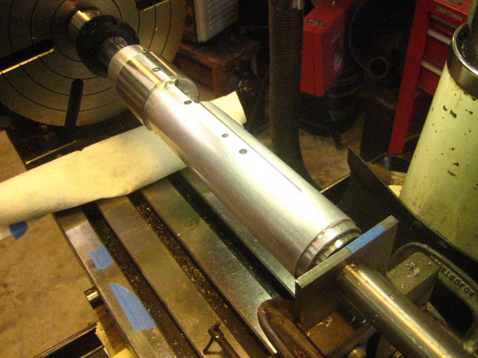
After all this time the testing begins. Shown here is the prototype frame with the mount and the first, of three, W52 barrel-receivers to test. The frame has been revised three times since the one shown here; however, the concept remains identical. Really, this is the cullmination of three years of effort on my behalf and considerable engineering activities.  Initially, my efforts were with the Federal 711B, which the shooting community consensus seems to denigrate. This formed my baseline. Things must get better from this baseline. This investigation is NOT designed to test the ammunition but the barrel-receiver combo vs ammunition.

The absolute goal is to compete prone, while I still can; however, my intention is to be competitive and the Sitman stocked Win 52 is not even close, which involved more than a year to accomplish. First of all Alex Sitman is not known to be quick or punctual; however, the results are uncompromised and I possess a high respect for his work ethic and honesty. Essentially, I know I must rebarrel the Sitman W52; but I can just "drop in" a barrel action combo for my own practice and I'm running out of time. Later I will add a Shillen barrel. Bill Blankenship, 8 time US bulleye champion who I was fortunate to meet, once told me not to practice with unknown and questionable gear. So I had Jim Clark build me 3-1911's over a 5 year period, two of which I have sold. Getting back to the W52:

http://www.accurateshooter.com/guns-of-week/22lr-rimfire-ammo-comparison-test/

The results are fascinating to say the least. The tester observed: “I got some amazing groups, and some which are, frankly, are absurdly bad! This has re-enforced what I had experienced with 22 ammo in the past — that is being consistently inconsistent.”

The procedure utilized was based upon a thorough general testing of more than 100 types of 22LR in very "sanitized" conditions. See the Accurate Shooter link above.

CONDITIONS
Over a period of 2 weeks and three days of testing 1) concept evaulation 2) FED 711B testing and 3) selected available brands carried by Midway USA.  The distance is 100 yds. The weather was great: 60^ to 80^ with winds less than 8 mph at ground level.  September 15, 2012 and September 22-23, 2012.

20 shot groups were observed, although at times I miscounted and the count was 18 or 19. Standard deviation was computed for the group, center of mass and error from the mean. The position of each round was measure to within .003".  One brush through the bore every 20 rds. Yes, this is achievable and here is how.


Here is a Remington Target 1080 fps. I never did reproduce this after this group. The light line to the left of the scan is exactly 3.000" + or - 0.015". Very symmetrical.  The Rem round is very tight in the W52 chamber, any W52 chamber. It is dirty. I have fired several thousand, waste of money, and time, which I do not have.


The pixel size is 0.003".  The green dot is the center of the group. The dotted lines are one standard deviation.


Rem 09/15/12
                         del X delY
1 240741.034 239937.067 0.391 -0.988
2 240740.917 239936.776 0.508 -0.697
3 240740.749 239936.540 0.676 -0.461
4 240740.987 239936.279 0.438 -0.200
5 240741.143 239936.426 0.282 -0.347
6 240741.539 239936.754 -0.114 -0.675
7 240742.045 239936.577 -0.620 -0.499
8 240742.072 239936.342 -0.647 -0.264
9 240741.970 239936.233 -0.545 -0.155
10 240741.660 239936.108 -0.235 -.029
11 240741.360 239935.913 0.065 0.166
12 240741.556 239935.860 -0.131 0.219
13 240741.625 239935.829 -0.200 0.250
14 240742.299 239936.100 -0.874 -.021
15 240741.776 239935.634 -0.351 0.444
16 240741.553 239935.551 -0.128 0.527
17 240740.597 239935.615 0.828 0.464
18 240740.477 239935.919 0.948 0.160
19 240741.405 239934.950 0.020 1.129
20 240741.735 239935.104 -0.310 0.975
 4814828.4985 4798721.576
                           

                            Left   Dn
 240741.424 239936.0788   -0.8743 -0.9880
                           0.9475  1.1292
 0.4975 0.5345              Right  Up
           Extreme Spread  1.8218 2.1172 inches


From the above and based upon this group, 66 2/3 out of 100 of the shots should be 0.498" left or right and 0.534 inches up or down from the center of the group and extreme spread 1.82" and 2.12" respectively. This score is 199-4X if held perfectly. And the next 20 rds in that box, much less the next box, who knows?

How did I do this?
Each target was scanned at 300 dpi. The scanned document was loaded into Bentley's  Microstation V8 Series 1 (Autocad has the same capabilities). A program written in Microsoft Visual basic then interrogated the file and extracted the coordinates in inches and the Cg computed and the other characteristics developed.  Press the "Easy" button.m Well for one group.


 TEST FRAME

The test frame evolved for more than a year and I will discuss some of the assumptions devised during the use thereof. But first a limited portion:

711B 09/15/12 STDx   STDy  delX   delY
             0.6132 0.6731 2.1022 2.5787
             0.6170 0.5299 2.2099 2.0216
             0.5346 0.9687 1.9126 3.4397

Rem Target   0.4976 0.5345 1.8218 2.1172

RWS          0.4651 0.4416 1.5126 1.4548
WIN T22      0.4837 0.8626 2.0810 3.3120

Laupa CentX  0.4592 0.3998 1.5367 1.9374
ELEY TEAM    0.5524 0.3374 1.9518 1.0745

FED um22     0.4018 0.4083 1.4279 1.5819
FED 922A     0.4484 0.4559 1.7888 1.6606
922A w/bbl   0.6115 0.5230 2.2507 2.1063
tuner

From this stage VarmintAL pages gave me guidance with his deterministic evaluation of a 22LR with and w/o a tuner. Originally, my hope was I could "tune" one of the W52 action-barrel. He did not perform verification of his model as stated elsewhere; but, I am not a novice at finite element analysis, albeit from a structural design environment. Material mechanics is an entire different discipline. Whereas structural is based upon "satisfactory performance", engineering mechanics ascertains actual conditions. I bow to his expertise.

look at the final frame:

This picture is "busy"; this was the last day of testing. Beneath the shop rag is a 95 lb lead weight. I made another one, 53 lbs, for the front leg and then added the 2" structural angle as a diagonal brace. All these modifications intended to add stiffness to the frame. Without the barrelled action, the frame does not exhibit, after a good "whomp" any sustained vibrations, so it alone is independent. Add the barrelled action, give it a "whomp" and the vibrations dampen for 2 seconds.
Receiver-Frame Connection Figure-XX
All of this is dependent upon the bullet exit time. Look at the RWS above data, about 1200 fps. This was a minimal group, only 10 rds (all I had). 3 rds were fliers, but look at the other hits. So maybe the time of flight has improved based upon the naked barrel harmonics. This round deserves more investigation.
To the right is a photo of the action connection to the frame. As discussed elsewhere, the rear of the W52 action has minimal stiffness. The open frame cannot reduce this deficiency; whereas the Eliseo stocked W52 will engage the cylinder. Qualitatively, the barrel harmonics will be subsequently reduced. Maybe AL can tell me how much. This avenue is not complete and I will add more info.
Futhermore, the open frame may have exerbated the rear bolt weakness. See Fig XX.


 The above will be my final condition and the rear screw affect will be minimal; thus the conditions tested herein are the before condition.

Also, from the above data, the receiver-barrel tested will not get me into the top 5. Most likely I will have to rebarrel.

First I am going to test one more action.

Then try to compensate the barrel harmonics with a tuner using the high velocity and low velocity methodology discussed on Accurate Shooter forum.

These items to come in a subsequent post.

ABSOLUTE FIXITY IN A TEST FRAME
Lastly. 
Consider the absolutely rigid mount (as I have devised here) for a moment vs. the bench rest shooting community. Once again, fixity (if possible) would resemble the testing performed in England by a 22 ammo manufacturer. Their testing clamped a barrel in a solid steel frame attached to concrete. The action was aft of the clamp and only 18" of the barrel protruded. The postulation was measurement of the barrel end frequency with light. Now, this would be very rigid boundary conditions. Even the barrel was shortened and thus subject to high frequencies.

Did I do this very same thing, albeit a flexible barrel? I dont know.

Bench rest shooters slide on rails, on special front rests, on special bags to specific density. Only the trigger finger and the shoulder touches the rig. They shoot groups the size of the 22 projectile under consideration herein.

In retrospect, let us consider the frame I have devised. But the connections are elastic. Between 2 plates of stainless steel, we bond an isolation rubber, i.e. laminated elastomeric bearing. The plywood shown in the photo is replaced by this bearing(s). The clamp would be justapositioned above the bearing. I think this is the way VarmintAl is modeling his boundary conditions. Well worth the modification. 

See: http://winchester52.blogspot.com/2012/09/continued-testing.html
It seems as though my overactive engineering mind overestimated the degree of fixity. The comments above are valid theoretically, the magnitude did not affect final result.

Added 10-05-2012 9:05 AM

The above concerns are not an 'overactive engineering mind' as discovered by others and hundreds of man-hrs have been devoted to analysis.

See: http://www.varmintal.com/  for thorough compendium on deterministic prediction of muzzle movement and orientation. This study helps us visualize the parameters involved and the relative affects.

For actual testing see:

    http://www.border-barrels.com/articles/rimfire_accuracy/tuning_a_barrel.htm

   http://www.border-barrels.com/articles/rimfire_accuracy/velocity_dispersion.htm

The latter is a long discourse concerning the vibrations of a "fixed" base such as I have constructed. My thoughts on the elastomeric connections was incorporated.

My goal is to find a combination of ammo-receiver-barrel that will amke me competitive. One thing I have learned: there may be a seperate setup for 50 yds.

to Quote:

The test rig had been built to be a rigid 'barrel vice', but it was plain that bottom plate flexed due to the recoil force. When looking through the scope (attached to the top of the barrel clamp) the picture would 'jump' noticeably when the rifle was fired. Free recoil test gun It was of concern that the recoil energy in the test rig was being dissipated in an unpredictable fashion into barrel vibrations that were affecting the group. In an effort to control the recoil energy in a predictable way, the Border Barrels Recoil Pressure Gun was adapted to make a free recoil test gun. With this gun, the recoil is constrained to be straight back, with the recoil energy being dissipated in friction by the linear slides on the rods and in the hydraulic damper seen at the back of the rig. The carriage is designed so that the centre of gravity of the recoiling mass is approximately on the bore line, so minimising any rotational moments when recoiling which might affect the launch angle of the bullet. Groups with this free recoil rig were initially disappointing as they formed vertical strings. The barrel and action were indexed 90 degrees to the left and to then to the right, but the groups produced were always strung vertically. Any systematic problem with the barrel and action was thus ruled out as the cause of the vertical stringing.

However, the barrel is vibrating before the bullet leaves the barrel. How we compensate is endless. This discussion used only two types of ammunition.  The 1/2" plate they used is flexible; my frame is flexible. However, I look at this in another manner. The frame(s) are very rigid; but the induced vibrations intiated by the burning gases transmits forces to the frames(s). Stocked and in the shooters hands, the results are more compliant. Consequently, we have only scratched the surface in 80 years for 22 RF.

End edit 10-05-2012.


A NOTE ABOUT W52 BOLT REMOVAL AND REPLACEMENT

 This topic is covered in many places; in no instance have I found an easy solution. One aspect is to understand the trigger. Look at this:
  • Everyone can remove the bolt, even in competition. So how do you get the blasted thing back in the receiver?  Push the easy button.
  • Look at the Photo to the right.
  • FIRST you must pull on the trigger to release the disconnector with right hand.
  • Second, hold the bolt in the right hand and aligned keeping finger on trigger.
  • Third, take the index finger of the left hand and with the nail down.
  • Fourth, Insert the finger into the receiver finger pointed to the rear.
  • Fifth, depress the top trigger lever with the thumb nail.
  • Sixth, with the right hand, while holding the trigger back, slide the bolt handle forward.  
This method was taught to me by the Army sargent supervising the UoA Cadet range. It takes practice. It works every time.

Mike
All rights reserved.


Friday, March 23, 2012

BUILDING THE ELISEO-WINCHESTER STOCK


SUMMARY

Late in life, we tend to start "bucket lists". After reading about the sensational success of the F Class matches, my subconscious began to whisper "you can do that, you can do that". Along came an Eliseo stock in 308. Damage from a recent surgery blunder compromised my ability to withstand the recoil. The following year, my wife gave me a Winchester 52D for my birthday and I remembered shooting prone with the W52 many years ago quite successfully. So would not the W52 be good training for FClass? Access to a 130 yd range added justification, too close for FClass and precisely challenging for 22RF. Alex Sitman built me an excellent prone stock for the W52D. My Eliseo 308, chambered by by Pierce Engineering, defined the scope of work, an Eliseo-Winchester 52D stock. One for CF, one for RF training. Thus began a 3 year quest. And considerable naivete. One caveat, my profession is civil engineering and surveying. No one should assume that I have expertise as a machinist.

INTRODUCTION

My wife gave me a Winchester 52D for my birthday. Sanding, Sanding, sanding rub rub sand yielded an excellent looking stock. Then checker, checker and checker. The result was less than my expectations but more than my ability at the time.


Winchwester 52D after Stock and chamber "enhancements"

Six months of shooting convinced me that the rifle looked good but would not shoot. Generally at 100 yds the groups would be 2" windage and 1" vertical on a good day that I did not make a mistake. Many times I could see the round going downrange rise 10" and spiral to the right into the target. Ammunition experimentation did not seem to offer an improvement and testing with harmonic tuners did not return repeatable reduction in group size. After much consternation, I decided to rebuild the W52. The barreled receiver was sent to Alex Sitman at MasterClass Stocks and after molding Alex returned the action. The action was then shipped to LA.

To the range with the 22RF: The rechambered barrel made a distinctive change in the group size...worse...now 7" at 100 yds. What a blunder and disappointment. The new chamber did not score the bullet nose. I knew the result before I fired it.


My instruction was to set the barrel back one thread and to rechamber with a Meyer reamer per Dave Kiff. One year later both the stock and barreled action were finally back in my hands. Several excursions with the Eliseo-Pierce 308 convinced me my 22RF effort was well worth it.


Figure -1-
Figure -2-


First, from my engineering experience, a numerical model of the receiver had to be constructed. The resulting computer model is shown as Figure -2-. The layout used to develop the "model" is shown as FIGURE -1-. Figure -1- was developed by wrapping the receiver with 0.003" bond paper gently tapping the surface with a wooden dowel. The second phase was cutting the indentations with an exacto knife and scanning the result at 1200 dpi. Thus the 2D "surface" represents the receiver 0.006" over diameter. From that point I wrote a computer program in Visual Basic 61 to convert the 2D representation into 3D coordinates and imported the resulting coordinates into Microstation2, a graphics production tool applicable to multiple disciplines, architecture, civil engineering, mechanical engineering and electrical engineering to name only a few. This created Figure -2-. Figure -1- was then scaled in the X direction proportional to the ratio of the (Stock OD)/(Recv OD). Once scaled the program resolved the detailed 2D dimensions into 3D. See Figure -4A-.

<><><><><><><> Microstation </>
Cutting Loading Port

Along with this the actual position of the cutting tool can be considered and careful consideration is required. As the tool penetrates the outer stock surface toward the receiver ports direct axial position cannot be assumed due to the diameter of the tool. Before recognizing this geometrical aspect my prior assumption caused removal of material not desired AND at least one prototype to the trash bin.
Before we get too far with the milling aspects of the project, all the lathe
operations should have been very simple; however, my new Jet 13X40 GHL could not bore a hole concentric with an OD. Much of my complaints ignored.


SEE
 http://www.jettools.com/us/manufacturing/en/product.html?node=4642&product=361822

The last set of definitions required the profile of the bolt lever and its intersection with the STOCK surface. Thus I started by measuring the profile of the bolt using the lathe digital readout and then translating those measurements related to the centerline of the receiver. See Figure 2. At this stage all the geometry has been identified for use in the 1) lathe or 2) on the mill. At least I thought.

RECEIVER-STOCK CONCEPT

Figure -4A-
Needlessly, tube based stocks did not originate with the writer and I possess two(2) of Gary Eliseo’s products, one a repeater and the other a solid frame. Once a thorough examination of the Winchester 52 receiver has been made the innate engineering characteristics become apparent. Qualitatively, the moment of inertia is less than 1/5 of the section at the front bolt. The reactions points and the section properties highly influence the vibrational response of the beam (barrel). Also as we term the "boundary conditions" also highly influence the barrel response to applied transient forces. These are the connections to the stock assembly. Refined structural analysis, in the form of a procedure called Finite Elements, can predict the change in response of the system (called a model) versus a physical change in the overall structure (barrel + receiver + stock). Many times the complexity of the model requires verification of the FE analysis in the form of measured deflections to any applied force. This is termed parameter calibration. The procedure outlined above is a quantitative procedure. Resources necessary to measure very small deformations require sophisticated electronic equipment. A firm based in England has pursued concept. Any attempt to perform a FE analysis without parameter verification would be qualitative and subjective in nature, for complex shapes. Many regular shapes can be evaluated with high confidence. Past experience warrents "educated guesses".


Cross Section at Rear Bolt
Therefore my judgement tells me to stiffen the boundary conditions. The photo on the right shows the "wrap" of the 2D file on the prototype stock. The photo on the left shows my design to make a positive affect to the boundary conditions. The sleeve is stainless steel. Above the sleeve is the prototype aluminum stock. Once the sleeve is cut to length, the sleeve (interference) fits over the muzzle end of the stock into a relief cut. The sleeve OD is 2.20", stock is 2.00" OD as Gary E’s. The bar in the back constitutes a mandrel for the steady rest and/or a tailstock livecenter.
REAR ACTION BOLT


Figure -5-
The sleeve enhances the forward receiver bolt connection and must terminate at the loading port forward position. The stock itself is then connected with the Winchester bolts and in addition allen head screws torqued against the upper receiver surface enforces contact and stiffness. One set screw engages the sleeve near, and above, the forward receiver screw and the second screw contacts the milled flat at the back of the receiver at the bolt handle near side. There are other methods to attain greater integrity I am presently investigating. Later.

FIGURE -6-
Figure -6- represents unfinished receiver-stock with trigger assembled with Eliseo's rail in the white.


MACHINING OPERATIONS
The Lathe

Figure -7-

The unfinished stock  is shown in Figure -7-  after final finishing to OD, both stock and the SS sleeve. Mandrels have been cut and finished for both the barrel end and the buttstock end. Buttstock is toward the reader.
The singlemost difficult aspect of the lathe operations involved boring a 1.230" hole into a 2" dia aluminum bar stock 10" long, uniformly. Jet Tools (3) can provide a medium priced lathe capable of precise work; however, for all you neophytes, be warned. The headstock vs. ways vs. tailstock will not be aligned. Furthermore they will not warrant the Q/C certification issued by the factory. The warranty period is 2 years. Realistically, this issue is beyond the scope of this discussion and regardless, from an involvement aspect, this issue created an unseemingly endless task of several hundred hours. Enough. More definitive descriptions will be later published.

Figure -7A- The End Bushings for the 1" dia shaft
Boring operations require a through bore 0.003" to 0.008" above receiver diameter. The buttstock end is 1.6" ID + 0.002". Mandrels for the buttstock is 1.600" OD with a 1.002" ID wheraes the barrel end has a mandrel of 1.233" OD and a 1.003" ID. Then a 1.00" OD shaft will penetrate as shown in Figure -7-. Both turning and mill operations benefit. The fitting of the sleeve and finish turning of the stock section are minor involvements.


The Mill Operations

My mill is not really a mill, JET terms is a drill-mill. Drilling is easily performed. Milling is complicated by the motion (flexibility) of the stand. The motor torque at startup moves the quill location and vibration can damamge the work. The stand is inadequate. Plans are on hand to remedy this situation.  Look at the mill-stock setup I devised, Figure 8. Let me explain. The rotary table on the left is 10" with a Shars ER-40 1" collet and MT3 chuck. On the right is an adjustable tailstock comprising a 1" thick angle bracket. Barely visible is a 1/4" plate,with 1.003" hole, clamped to the bracket. This jigging yields bi-directional location at the tailstock. The stock is now ready for all holes to be drilled (with some tapped). This phase of the build constituted many errors on my behalf. At this stage the system model has been defined as a 3D cartesian coordinate system (with Microstation). To make the rotary table most useful a 3D cylindrial system is advantageous so a cartesian to cylindrical system transformation was required.

Figure -8-
Figure -8- Milling Jig

Also, at this point I assumed all the holes and the slot for the sight ramp milled. I was incorrect which caused considerable trial and error cuts which, in retrospect, was wasted time and effort. I'll explain. My comfort with geometry was not followed through to the final step because I anticipated visualization of the final product.  Well, this was not correct because I did not anticipate the proper position of the bolt lever arm slot.


FIGURE -9-
This all gets back to the first three letters of assume. For an engineer, my logic was seriously flawed. I did not carry my computer model to final assembly. This failure, on my behalf, cost many man-hours at the mill.
The measurement of the bolt handle through cut was accomplished with the annular ring seen in Figure 4A. Also see Figure -7A-. The ID fits the receiver OD by +0.003". Orthogonal axes are scribed on the ring. Then the piece is placed on the receiver with bolt installed, the handle moved through the complete movement and the upper and lower limits marked on the ring. 
Fig -11- Slot and holes


The holes that Gary E used conflicted with positions of my action torque screws, and penetrated the bolt handle slot. The slot cut was too deep and a myriad of other complications.


The inside mandrel

In order to facilitate all operations the inside mandrel must be smaller than the actual ID, 1.230 inches. The 1" round adds sufficient stiffness.  At this point the coordinates must revert back to cylindrical coordinates that will be appropriate for the rotary table. One aspect at this stage: Once the part is removed from the fixture aligning vertical axis with the part is difficult. The horizontal axis was simple. Gary E told me the best is not to remove the part.


The final operation is cutting the grip.
See the whoops on the table! Not good.


1)  Copyright Microsoft Corp., Microsoft Visual Basic 6.0, 1987
2)  http://www.bentley.com/en-US/
3) http://www.jettools.com/us/manufacturing/en/about_us/contact_us.html